

DD-WRT: Configuring for Home with OSPF and Multiple VLAN’s.
Fast forward a few years, and after a few IoT device purchases, multiple VLAN setup with DD-WRT started to become more attractive. More importantly, a friend asked about the same so I’ve set out to do just that: setup additional VLAN’s for my own network via DD-WRT. Why would I want to do this? For the simple fact that multiple VLAN’s offer less chance of IP conflicts and on a single congested network, things tend to slow down alot in a single VLAN. This is where multiple VLAN’s come in handy.
If you wish to skip the entire tutorial, feel free to jump towards the end of the article to download the template for DD-WRT with all the configuration settings pre-set for you. Word of thought however. Going through the setup manually has the advantage of introducing the reader to the inner workings of each settings.
For this setup, we will use DD-WRT r48128, which looks to be a very stable release. The router used is the:
Asus RT-AC88U
with the Broadcom BCM4709 chip. However, given that DD-WRT’s fairly universal setup, it’s not a far stretch to think this will also work on other similar units. First, a quick disclaimer:
These settings are only for Proof Of Concept (POC) LAB setup that is NOT meant to be internet facing in anyway. The setup here requires significantly more configuration before it can be considered OR used in any environment aside from a POC LAB environment.
Before jumping in, it’s noteworthy to mention the ports to be used once the setup is complete:
| Service | IP:Port |
| SSH (Local Network) | 192.168.0.19:56565 |
| Remote GUI (HTTPS)
Only if Internet Facing. |
EXTERNAL IP:10101 |
| SSH (Remote) | EXTERNAL IP:10102 |
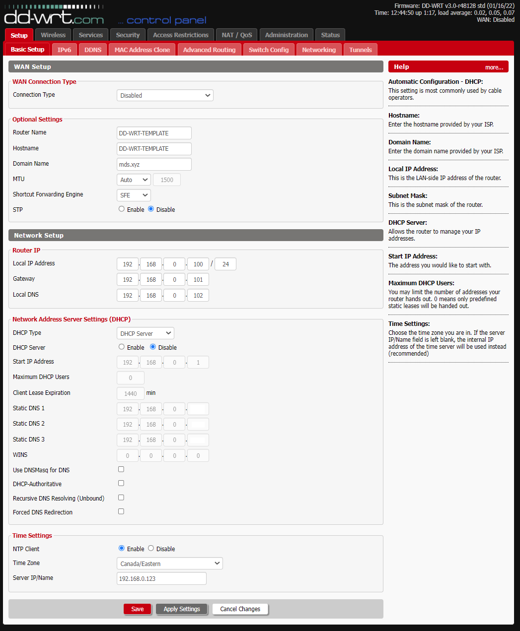
So now on to the setup. First, set your basic configuration as follows:
Router Name: DD-WRT-TEMPLATE
Hostname: DD-WRT-TEMPLATE
Domain Name: mds.xyz
MTU: Auto
Shortcut Forwarding Engine: SFE
STP: Disable
Router IP: Choose one. Image Sample: 192.168.0.100/24
Gateway: Choose one. Image Sample: 192.168.0.101. Typically this is X.X.X.1 .
Local DNS: Use your local DNS Server here. Image sample: 192.168.0.102
DHCP Type: We probably don’t really need the DHCP server running here but haven’t tested with this option set differently. For now, this can be selected but disabled. DHCP will be ran manually later on.
Static DNS 1-3: Fill these in with the local DNS servers available on your network. Leave blank if none.
NTP Client: Enable (If you have one)
Time Zone: Canada / Eastern
Server IP/Name: 192.168.0.123 (If you have one)
Next, let’s look at the Advanced Routing section. In this case, OSPF will be configured and used. IMPORTANT: This assumes the rest of your routers will also run OSPF, including your internet facing router. OSPF will transfer the VLAN information to the rest of your routers enabling you to access said VLAN’s anywhere in your setup.
Operating Mode: OSPF Router
OSPF Config Style: GUI
OSPF Configuration: (Paste Contents Below)
router ospf
log-adjacency-changes
ospf router-id 192.168.0.100
network 192.168.0.1/24 area 0
network 10.4.0.1/24 area 0
network 10.5.0.1/24 area 0
#
# debug ospf ism
# debug ospf lsa
# debug ospf nsm
# debug ospf nssa
# debug ospf packet all
# debug ospf sr
# debug ospf te
# debug ospf zebra
#
log file /var/log/ospf
hostname DD-WRT-TEMPLATE
Zebra Config Style: GUI
Zebra Log: Enabled

Save the config. Let’s move along ot the Switch Config. We will assign a couple of VLAN’s to various physical ports as well. If missing VLAN 3 and 4, add these in and set them accordingly for the various ports. There is no specific need to assign the ports to a different VLAN, as in the second image, however for the purpose of this demonstration, we will assign these to give our physical interfaces the capability to to access above said VLAN’s.

Example of a config that does not assign the new VLAN’s to the physical ports:

Next, define your Wireless Interfaces. In our case, we’ve defined 6. Three for 2.4Ghz and 3 for 5Ghz, each on a separate VLAN.
Wireless Mode: AP
Wireless Network Mode: Mixed
Wireless Network Name (SSID): NVLAN192168-2.4
Wireless Channel: Auto
Channel Width: Wide HT40 (40 MHz)
Extension Channel: lower
Wireless SSID Broadcast: Disable
TurboQAM (QAM256) support: Enable
NitroQAM (QAM1024) support: Disable
Explicit BeamformingEnable: Disable
Implicit BeamformingEnable: Disable
Airtime Fairness: Disable
Sensitivity Range (ACK Timing): 500 (Default: 500 meters)
Wireless GUI Access: Enable
Multicast To Unicast: Disable
Network ConfigurationU: Bridged
In addition, define two Virtual AP’s for the two VLAN’s we will setup here. The naming convention used for this demo is NVLAN[X][X]-[2.5|5 Ghz] . Any valid name will do however in this article, recommending to set a consistent name that’s easy to follow.

The same configuration, however for the 5.0Ghz frequency:

Save the configuration. Next, head on over to the Wireless Security settings page. Recommendation is to set these as high as possible to give you the best encryption available.
Security Mode: WPA2-PSK
WPA Algorithms: CCMP-128 (AES)
WPA Shared Key: ***********************************
Key Renewal Interval (in seconds): 3600

Note the Wireless interfaces above, such as wl0.1, wl0.2, wl1.1 and wl1.2. This will be used and very important in the Networking section where we will associate these to each VLAN.
Next, let’s head an over to the Services Page. The services page is not super critical to the setup but we’ll go over these anyway since it’s noteworthy for those running more elaborate home environments. Of particular interest is the SSH Service enablement, log server and Zabbix server monitoring, if these are desired or available.
SNMP
SNMP: Enable
Location: LROOM
Contact: root
Name: DD-WRT-TEMPLATE
RO Community: public
RW Community: private
Secure Shell
SSHd: Enable
SSH TCP Forwarding: Disable
Password Login: Enable
Port: 56565 (Default: 22)
Authorized Keys
System Log
Syslogd: Enable
Klogd: Enable
Remote Server: 192.168.0.150
Zabbix
Client: Enable
Zabbix Server IP: 192.168.0.111
User Parameters


Next, let’s head on over to the Services USB configuration page. This is very usefull especially since enabling JFFS and including an EXT3 or EXT4 formatted USB an add gigabytes of space to your router. If a USB stick is available.
USB Support
Core USB Support: Enable
USB Printer Support: Enable
USB Storage Support: Enable
Drive Read-Ahead buffer in sectors: 256
USB Over IP: Enable
Automatic Drive Mount: Enable
Run-on-mount Script Name: EMPTY
Mount this Partition to /jffs: EMPTY (Default) UUID
Mount this Partition to /opt: EMPTY (Default) UUID
Use SES Button to remove drives: Enable

It’s advisable to also spend a bit of time on security as well. Head on over to the Security Firewall section and let’s predefine some default settings to harden the setup. IMPORTANT: These are by no means complete or the most secure settings. Of particular interest, are the following:
Firewall Protection
SPI Firewall: Enable
Additional Filters
Filter Proxy: UNCHECKED
Filter Cookies: UNCHECKED
Filter Java Applets: UNCHECKED
Filter ActiveX: UNCHECKED
Filter TOS/DSCP: UNCHECKED
ARP Spoofing Protection: CHECKED
Block WAN Requests
Block Anonymous WAN Requests (ping): CHECKED
Filter Multicast: CHECKED
Filter WAN NAT Redirection: UNCHECKED
Filter IDENT (Port 113): CHECKED
Block WAN SNMP access: CHECKED
Impede WAN DoS/Bruteforce
Limit SSH Access: CHECKED
Limit Telnet Access: CHECKED
Limit PPTP Server Access: CHECKED
Limit FTP Server Access: CHECKED
Log
Log: Enable
Log Level: Low

The Administration Management section is where you will want to define a few access defaults while selecting alternative ports in the process, to yet further harden the setup. Of particular interest is the HTTPS and port configuration:
Web Access
Protocol: HTTP HTTPS
Auto-Refresh (in seconds): 3
Enable Info Site: Enable
Info Site Password Protection: UNCHECKED
Info Site MAC Masking: Enable
Remote Access
Web GUI Management: Enable
Use HTTPS: CHECKED
Web GUI Port: 10101 (Default: 8080, Range: 1 – 65535)
SSH Management: Enable
SSH Remote Port: 10102 (Default: 22, Range: 1 – 65535)
Telnet Management: Disable
Allow Any Remote IP: Enable
JFFS2 Support
Internal Flash Storage: Enable
Clean Internal Flash Storage: Disable
Total / Free Size
100.66 MB / 98.20 MB
Cron
Cron: Enable
Additional Cron Jobs
# Reboot the router everyday near 1AM.
17 1 * * * startservice run_rc_shutdown; /sbin/reboot
The remainder of the settings are largely preferencial:


Heading over to the Administration Commands section, we enter two of the most important sections of the setup where we define the DHCPD daemon and detailed Firewall configuration for use on our unit. The idea behind the setup is to allow only what is known and deny everything else, including traffic that are not known. Since most of the setup is in text, it is listed below for convenience:
Startup
udhcpc -i vlan3 -p /var/run/udhcpc.pid -s /tmp/udhcpc -O routes -O msstaticroutes -O staticroutes -H DD-WRT-TCRATES &
udhcpc -i vlan4 -p /var/run/udhcpc.pid -s /tmp/udhcpc -O routes -O msstaticroutes -O staticroutes -H DD-WRT-TCRATES &
Firewall
# ———————-
# ICMP – Allow ICMP TYPE 0 – Echo reply from outside.
# ———————-
iptables -A INPUT -p 89 -j ACCEPT
iptables -A OUTPUT -p 89 -j ACCEPT
# ———————-
# ICMP – Allow ICMP TYPE 0 – Echo reply from outside.
# ———————-
iptables -A INPUT -p icmp –icmp-type 3 -s $(nvram get wan_ipaddr) -d $(nvram get wan_ipaddr) -m state –state ESTABLISHED,RELATED -j ACCEPT
# ———————-
# ICMP – Allow ICMP TYPE 0 – Echo reply from outside.
# ———————-
iptables -A INPUT -p icmp –icmp-type 0 -d $(nvram get wan_ipaddr) -m state –state ESTABLISHED,RELATED -j ACCEPT
iptables -A INPUT -s 127.0.0.1 -d 127.0.0.1 -j ACCEPT
# ———————————
# ICMP – Allow inbound echo reply.
# ———————————
iptables -A INPUT -p icmp –icmp-type 0 -j ACCEPT
iptables -A OUTPUT -p icmp –icmp-type 0 -j ACCEPT
# ———————————–
# NAT Rules (from Gateway Config)
# Needed for web access.
# ———————————–
iptables -t nat -I POSTROUTING -s 192.168.100.0/24 -j SNAT –to $(nvram get wan_ipaddr)
iptables -t nat -I POSTROUTING -s 192.168.101.0/24 -j SNAT –to $(nvram get wan_ipaddr)
iptables -t nat -I POSTROUTING -s 10.4.0.0/24 -j SNAT –to $(nvram get wan_ipaddr)
iptables -t nat -I POSTROUTING -s 10.5.0.0/24 -j SNAT –to $(nvram get wan_ipaddr)
iptables -t nat -I POSTROUTING -s 192.168.0.0/24 -j SNAT –to $(nvram get wan_ipaddr)
iptables -t nat -I POSTROUTING -m mark –mark 0x80000000/0x80000000 -j MASQUERADE
# ———————-
# ICMP – 127.0.0.1
# ———————-
iptables -A INPUT -p icmp –icmp-type 0 -s 127.0.0.1 -d 127.0.0.1 -j ACCEPT
iptables -A OUTPUT -p icmp –icmp-type 0 -s 127.0.0.1 -d 127.0.0.1 -j ACCEPT
iptables -A INPUT -p icmp –icmp-type 8 -s 127.0.0.1 -d 127.0.0.1 -j ACCEPT
iptables -A OUTPUT -p icmp –icmp-type 8 -s 127.0.0.1 -d 127.0.0.1 -j ACCEPT
iptables -A INPUT -p icmp –icmp-type 3 -s 127.0.0.1 -d 127.0.0.1 -j ACCEPT
iptables -A OUTPUT -p icmp –icmp-type 3 -s 127.0.0.1 -d 127.0.0.1 -j ACCEPT
# ———————-
# ICMP – 192.168.0.X
# ———————-
iptables -A INPUT -p icmp –icmp-type 0 -s 192.168.0.0/24 -d 192.168.0.0/24 -j ACCEPT
iptables -A OUTPUT -p icmp –icmp-type 0 -s 192.168.0.0/24 -d 192.168.0.0/24 -j ACCEPT
iptables -A INPUT -p icmp –icmp-type 8 -s 192.168.0.0/24 -d 192.168.0.0/24 -j ACCEPT
iptables -A OUTPUT -p icmp –icmp-type 8 -s 192.168.0.0/24 -d 192.168.0.0/24 -j ACCEPT
iptables -A INPUT -p icmp –icmp-type 3 -s 192.168.0.0/24 -d 192.168.0.0/24 -j ACCEPT
iptables -A OUTPUT -p icmp –icmp-type 3 -s 192.168.0.0/24 -d 192.168.0.0/24 -j ACCEPT
# ———————-
# ICMP – 10.4.0.X
# ———————-
iptables -A INPUT -p icmp –icmp-type 0 -s 10.4.0.0/24 -d 192.168.0.0/24 -j ACCEPT
iptables -A OUTPUT -p icmp –icmp-type 0 -s 192.168.0.0/24 -d 10.4.0.0/24 -j ACCEPT
iptables -A INPUT -p icmp –icmp-type 8 -s 10.4.0.0/24 -d 192.168.0.0/24 -j ACCEPT
iptables -A OUTPUT -p icmp –icmp-type 8 -s 192.168.0.0/24 -d 10.4.0.0/24 -j ACCEPT
iptables -A INPUT -p icmp –icmp-type 3 -s 10.4.0.0/24 -d 192.168.0.0/24 -j ACCEPT
iptables -A OUTPUT -p icmp –icmp-type 3 -s 192.168.0.0/24 -d 10.4.0.0/24 -j ACCEPT
# ———————-
# ICMP – 10.5.0.X
# ———————-
iptables -A INPUT -p icmp –icmp-type 0 -s 10.5.0.0/24 -d 192.168.0.0/24 -j ACCEPT
iptables -A OUTPUT -p icmp –icmp-type 0 -s 192.168.0.0/24 -d 10.5.0.0/24 -j ACCEPT
iptables -A INPUT -p icmp –icmp-type 8 -s 10.5.0.0/24 -d 192.168.0.0/24 -j ACCEPT
iptables -A OUTPUT -p icmp –icmp-type 8 -s 192.168.0.0/24 -d 10.5.0.0/24 -j ACCEPT
iptables -A INPUT -p icmp –icmp-type 3 -s 10.5.0.0/24 -d 192.168.0.0/24 -j ACCEPT
iptables -A OUTPUT -p icmp –icmp-type 3 -s 192.168.0.0/24 -d 10.5.0.0/24 -j ACCEPT
# ———————–
# Allow guest bridge access to Internet
iptables -I FORWARD -i br2 -m state –state NEW -j ACCEPT
iptables -I FORWARD -i br1 -m state –state NEW -j ACCEPT
iptables -I FORWARD -p tcp –tcp-flags SYN,RST SYN -j TCPMSS –clamp-mss-to-pmtu
# Block access between private and guest (Allow for now – Need web access for 10.4.0.0/24 and 10.5.0.0/24 ) EXAMPLE BLOCK RULES
# iptables -I FORWARD -i br0 -o br1 -m state –state NEW -j DROP
# iptables -I FORWARD -i br1 -d `nvram get lan_ipaddr`/`nvram get lan_netmask` -m state –state NEW -j DROP
# NAT to make Internet work for both br0 (home wifi) and br1 (guest network)
iptables -t nat -I POSTROUTING -o br0 -j SNAT –to `nvram get lan_ipaddr`
iptables -t nat -I POSTROUTING -o br1 -j SNAT –to `nvram get lan_ipaddr`
iptables -t nat -I POSTROUTING -o br2 -j SNAT –to `nvram get lan_ipaddr`
# ———————————————————————————————
# Block torrent and p2p
# Change the IP address to the IP of your guest network x.x.x.x/24
# ———————————————————————————————
iptables -I FORWARD -p tcp -s 192.168.100.0/24 -m connlimit –connlimit-above 50 -j DROP
iptables -I FORWARD -p ! tcp -s 192.168.100.0/24 -m connlimit –connlimit-above 25 -j DROP
# Block guest access to router services ( Allow for VLAN 10.4.0.0/24 and 10.5.0.0/24 ) EXAMPLE BLOCK RULES
# iptables -I INPUT -i br1 -p tcp –dport telnet -j REJECT –reject-with tcp-reset
# iptables -I INPUT -i br1 -p tcp –dport ssh -j REJECT –reject-with tcp-reset
# iptables -I INPUT -i br1 -p tcp –dport www -j REJECT –reject-with tcp-reset
# iptables -I INPUT -i br1 -p tcp –dport https -j REJECT –reject-with tcp-reset
# ———————————————————————————————
# Remote Management / External Port / VPN Example / Port Forwarding Firewall Ports
# ———————————————————————————————
iptables -A INPUT -p tcp –dport 12345 -j ACCEPT
# ————————————-
# Basic services and local VLAN’s
# ————————————-
iptables -A FORWARD -s 192.168.0.0/16 -d 192.168.0.0/16 -p udp -j ACCEPT
iptables -A FORWARD -s 192.168.0.0/16 -d 192.168.0.0/16 -p tcp -j ACCEPT
iptables -A INPUT -s 192.168.0.0/16 -d 192.168.0.0/16 -p udp -j ACCEPT
iptables -A INPUT -s 192.168.0.0/16 -d 192.168.0.0/16 -p tcp -j ACCEPT
iptables -A OUTPUT -s 192.168.0.0/16 -d 192.168.0.0/16 -p udp -j ACCEPT
iptables -A OUTPUT -s 192.168.0.0/16 -d 192.168.0.0/16 -p tcp -j ACCEPT
iptables -A INPUT -s 0.0.0.0 -d 255.255.255.255 -p udp -j ACCEPT
iptables -A INPUT -s 0.0.0.0 -d 255.255.255.255 -p tcp -j ACCEPT
iptables -A INPUT -s 192.168.0.0/24 -d 255.255.255.255 -p udp -j ACCEPT
iptables -A INPUT -s 192.168.0.0/24 -d 255.255.255.255 -p tcp -j ACCEPT
iptables -A INPUT -s 10.4.0.0 -d 255.255.255.255 -p udp -j ACCEPT
iptables -A INPUT -s 10.4.0.0 -d 255.255.255.255 -p tcp -j ACCEPT
iptables -A INPUT -s 10.5.0.0 -d 255.255.255.255 -p udp -j ACCEPT
iptables -A INPUT -s 10.5.0.0 -d 255.255.255.255 -p tcp -j ACCEPT
# NTP
iptables -A OUTPUT -p udp –dport 123 -j ACCEPT
iptables -A INPUT -p udp –sport 123 -j ACCEPT
# ———————-
iptables -I INPUT -d 192.168.0.0/16 -s 192.168.0.0/16 -p udp –dport 68 -j logaccept
iptables -I INPUT -d 192.168.0.0/16 -s 192.168.0.0/16 -p udp –dport 67 -j logaccept
iptables -I INPUT -d 192.168.0.0/16 -s 192.168.0.0/16 -p tcp –dport 68 -j logaccept
iptables -I INPUT -d 192.168.0.0/16 -s 192.168.0.0/16 -p tcp –dport 67 -j logaccept
#
iptables -A OUTPUT -s 192.168.0.0/16 -p tcp –dport 22 -j ACCEPT
iptables -A OUTPUT -s 192.168.0.0/16 -p udp –dport 22 -j ACCEPT
# External IP example for SSH management.
iptables -A OUTPUT -s 100.100.100.100 -p tcp –dport 10101 -j ACCEPT
#
# ———————————————————————————————
# External access from specific IP ranges.
# ———————————————————————————————
iptables -A INPUT -s 192.168.0.0/16 -p tcp –dport 22 -j ACCEPT
iptables -A INPUT -s 192.168.0.0/16 -p udp –dport 22 -j ACCEPT
iptables -A INPUT -s 123.123.123.123 -p tcp –dport 10101 -j ACCEPT
iptables -A INPUT -s 123.123.123.123 -p udp –dport 10101 -j ACCEPT
iptables -A INPUT -s 123.123.123.123 -p tcp –dport 10102 -j ACCEPT
iptables -A INPUT -s 123.123.123.123 -p udp –dport 10102 -j ACCEPT
# —————————————————-
# Not really sure this is needed.
# At least it keeps the logs cleaner.
# —————————————————-
iptables -I INPUT 1 -p tcp –-dport 12345 -j ACCEPT
iptables -I FORWARD 1 –-source 10.1.1.0/24 -j ACCEPT
iptables -t nat -A POSTROUTING -s 10.1.1.0/24 -j MASQUERADE
# ———————-
# Accept Local VLAN’s
# ———————-
iptables -A INPUT -s 192.168.0.0/24 -j ACCEPT
iptables -A INPUT -s 10.4.0.0/24 -j ACCEPT
iptables -A INPUT -s 10.5.0.0/24 -j ACCEPT
# ———————-
iptables -P FORWARD logdrop
iptables -P INPUT logdrop
iptables -P OUT logdrop
# ———————-

Of note is that some of the highlighted IP’s and ports above are for example only. Meaning, these can be removed from the configuration in case they are not needed at all or don’t nake sense in an environment. Once more, save the configuration. Here, the final part of the configuration will be discussed since this is where we define our interfaces and also define where and how the VLAN’s are associated:
In the Create Bridge section, create br1 and br2. Set them accordingly to the image below and save the configuration. Next, allocate each Bridge to the Interface where you wish to assign each new VLAN created in the previous steps. Note that this goes hand in hand with the OSPF configuration above, where each VLAN entry was specified within the config for automatic route discovery. A unique name can be given to each bridge as in the below image as well, for easier tracking.


Save the configuration!
Assuming other routers within your network are running OSPF, test by pinging or connecting to one of the Physical or Wireless interfaces on your router.
Hope this helps and gives a brief overview of a multi VLAN configuration using DD-WRT.
Enjoy!
Not An Admin

